As appeared in Laser Focus World https://www.laserfocusworld.com/optics/article/16548272/optical-system-design-software-environment-creates-coherent-workflow-for-optical-system-design
Optical system design feels like the stepchild of the digital revolution. While powerful, intuitive, fast computer-based tools are available to engineers in fields from integrated-circuit layout to aircraft design and architecture, designers of optical systems are coping, for the most part, with antiquated software. Optical systems have numerous complex constraints and requirements—their challenges go beyond designing the perfect lens or excellent components.
The design process typically starts with rough, hand-drawn layouts, and ends with detailed specifications for vendors and mechanical and manufacturing engineers. But getting from the sketch to a detailed spec is painful, time-consuming, and requires using many disparate and disjointed tools. Existing optical-simulation tools, while effective for specialized applications, take significant amounts of time to provide answers and often lack interfaces for communicating with other tools. Designers struggle with suboptimal tools, especially during the earlier, iterative stages of the design process. For example, when simulating and evaluating the “rough draft” of a functional layout, the time involved can be impractically long using tools intended for detailed simulations.
A new design environment, called BeamWise, has been developed to address these longstanding problems. The software is intended to be an intuitive system design environment. It does not replace CAD systems or detailed optical modeling tools—rather, it integrates these tools into a coherent workflow for optical system design (see Fig. 1). Each tool thus can perform efficiently at what it does best for the benefit of the entire design process.
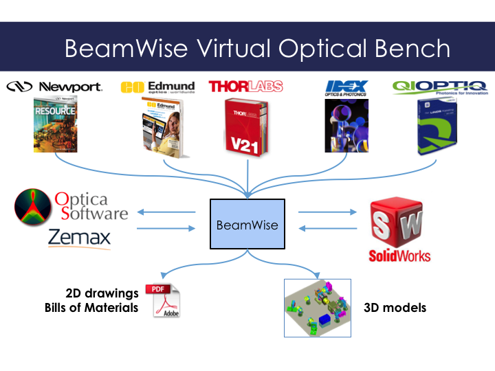
The BeamWise 3D Model, a “virtual optical bench,” can be seamlessly imported into CAD environments. Because it allows bidirectional interfacing with the other tools, designers can have real-time visualization, interactive change management, instant addressing of physical conflicts, efficient design reuse, and transparent capture of design intent. Real-world projects with the National Cancer Institute and other research groups have illustrated the power of this approach.
An improved design workflow
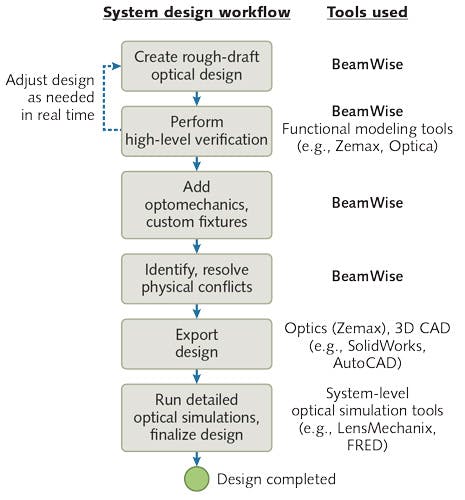
Using the software as a design tool for a complex optical system, engineers can quickly create a layout, verify the optical and mechanical aspects of the design interactively, and iterate to generate a near-final design for prototyping or production. The procedure provides the most useful feedback at the appropriate stage of the design process. Here is a typical workflow, which Fig. 2 summarizes:
1. Rough out a design. In the BeamWise environment, create a virtual optical bench in real time. The system concept, the equivalent of a hand-drawn sketch, is translated into a functional layout of optical components.
2. Perform high-level verification. Through bidirectional interfaces built into BeamWise, send the optical system prescription to simulation and optical modeling software such as Zemax OpticStudio or Optica. By focusing only on the essential elements, this stage can verify in real time that the design architecture is sound.
3. Iterate. Automatically import any modifications back into BeamWise and repeat the verification process as needed.
4. Add optomechanical fixturing. Use off-the-shelf components from catalogs such as those from Thorlabs, Newport, Edmund, and Qioptiq to support and integrate all the optical components, or incorporate custom parts from proprietary design files.
5. Analyze physical conflicts. Use BeamWise to identify and resolve any issues caused by mounting.
6. Export the system to design tools. Transmit the resulting complete system (optics and optomechanics) as a 3D file to CAD tools such as SolidWorks or AutoCAD for mechanical and manufacturing engineers to use. BeamWise can also generate 2D engineering drawings and bills of materials.
7. Analyze optical performance (optional). As the final step, export the results to optical analysis software such as LensMechanix, Code V, or FRED to run detailed simulations and perform stray-light analysis. Note that these simulations take a long time and cannot be iterated quickly.
Advantages of an integrated approach
As a system design tool, the software allows designers to visualize the entire optical and mechanical system before committing to specific hardware, cutting metal, or buying parts. This reduces redesign and rework, and eliminates the inconvenience and expense of parts returns and scrapping. The software provides an intelligent link to the optical layer, allowing bidirectional transfer of information to specialized optical modeling tools. Designers can take advantage of the capabilities of these tools knowing that no information has fallen through the cracks.
This approach also enables designers to reuse and recycle existing designs. Because components are anchored to the local optical axis, altering the baseline design to generate a derivative system is much faster than starting from scratch. The revised model still incorporates the intelligent optical path definitions used for bidirectional interfacing to specialized modeling tools.
Case studies
Professor John Nolan, then at La Jolla Bioengineering Institute (La Jolla, CA), wanted to reduce the risk of physical interference conflicts between optical components in a prototype instrument. BeamWise modeled the system to detect problems and provide recommendations for next steps, enabling the designers to scope and prioritize refinements to improve performance, robustness, and cost of the system.
Next, the instrument’s schematics and parts were incorporated into the software, which generated a beam-anchored CAD model of the mechanical components. The output further guided the design of a manufacturable version of the instrument. In addition to the improvements to the design, the engineers concluded that using BeamWise would make future design revisions more efficient.
Designing a custom flow cytometer for the National Cancer Institute involved creating an optical system design from scratch. Using BeamWise, designers at Kinetic River started by rapidly developing a layout of the functional optical components. They created a virtual optical bench (see Fig. 3) to visualize the architecture and identify potential issues early in the process, quickly iterating layout choices for functional and ergonomic considerations. The model was then exported as 3D file to a CAD environment to implement additional supports, verify the overall structure, and provide blueprints for assembly.(Courtesy of BeamWise)
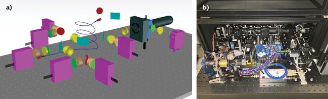
The software enabled the design process to proceed rapidly and efficiently through the early “what-if” stages. The resulting design remained stable through the rest of the project, with only few and minor tweaks introduced in the later stages of design and manufacture.